System Overview
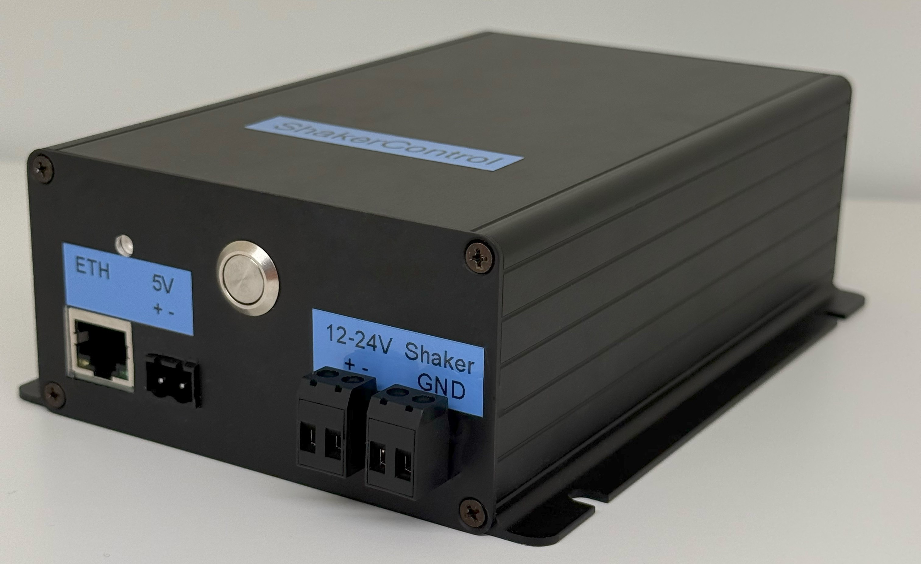
Welcome to the Shaker Control System. This professional-grade hardware and software solution is engineered specifically for monitoring and managing cinema shaker installations.
The system actively monitors the current consumption across multiple shaker strings (up to 10 separate strings). By analyzing real-time data, the controller can instantly detect anomalies such as:
- Overcurrent (Overpower): Detecting critical power spikes to protect the hardware.
- Shaker Degradation & Failures: Shakers are essentially electric motors. When they degrade, their internal resistance changes. The system detects these deviations—whether a shaker consumes abnormally low current (total failure) or abnormally high current (e.g., a blocked motor). This allows the early detection of creeping defects.
In the event of a fault, the system primarily informs the user by dispatching automated alerts via E-Mail or custom TCP webhooks to your central management servers. Furthermore, the system will always trigger an automatic physical cut-off to protect the hardware whenever the maximum allowable current is exceeded.
Hardware Limits & Specifications
To prevent permanent hardware damage and ensure stable continuous operation, you must strictly adhere to the limits below. Exceeding the maximum current or temperature thresholds can lead to thermal failure.
| Parameter | Absolute Maximum / Limit |
|---|---|
| Ambient Operating Temp. | 0°C to +45°C |
| Operating Voltage (Logic) | 5V DC / 12V – 24V DC |
| Operating Voltage (Shakers) | 0V – 24V DC |
| Maximum Current (Total) | 20.0 A (Do not exceed under any circumstances) |
| Maximum Current (Per String) | 2.0 A (2000 mA) |
| Network Interface | 10/100 Mbps Ethernet (RJ45) |
Connections & Wiring
The Shaker Control unit is divided into a front panel (Logic & Network) and a back panel (High-Power Shaker Terminals).
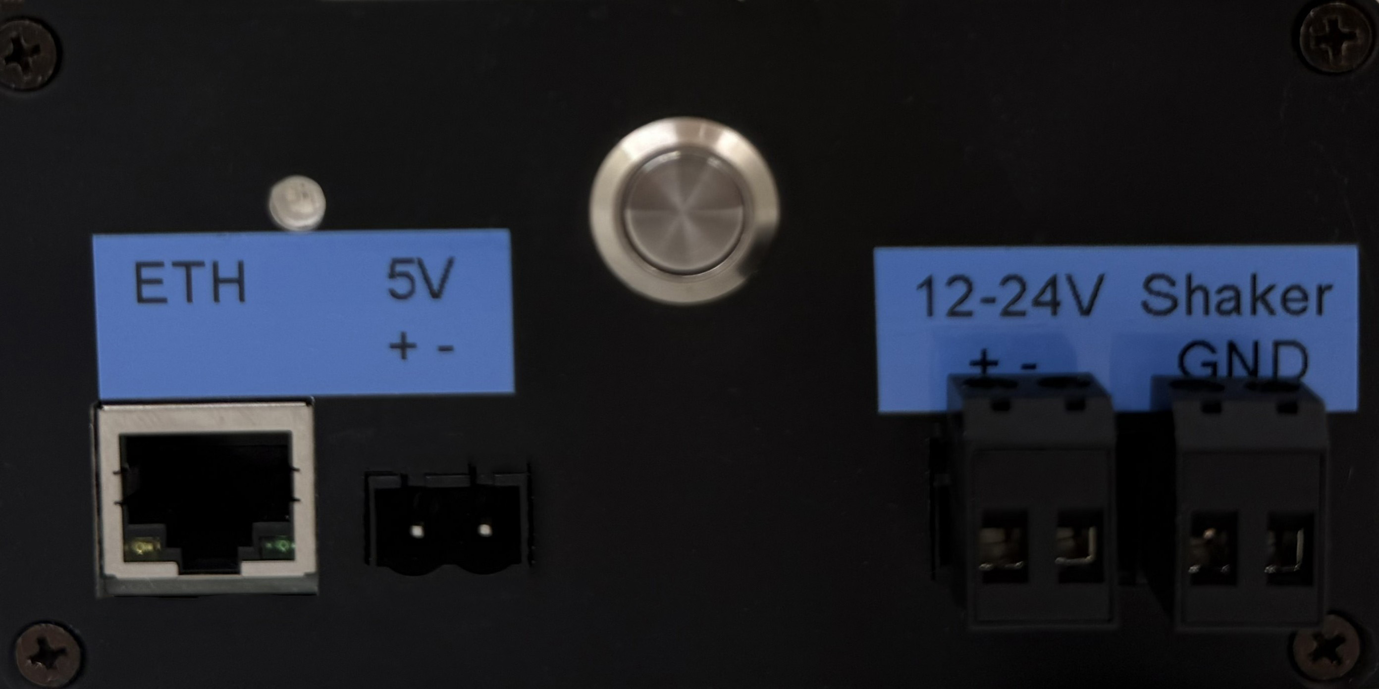
Front Panel
- ETH: Standard RJ45 port for local network connectivity. Required for Web UI and automated reporting.
- Redundant Power Supply Options: The logic board can be powered by the 5V +/- terminal, the 12-24V +/- terminal, or both simultaneously. The board features an internal switching circuit that will seamlessly failover between the two power sources without interruption.
- Shaker GND: Critical measurement ground.
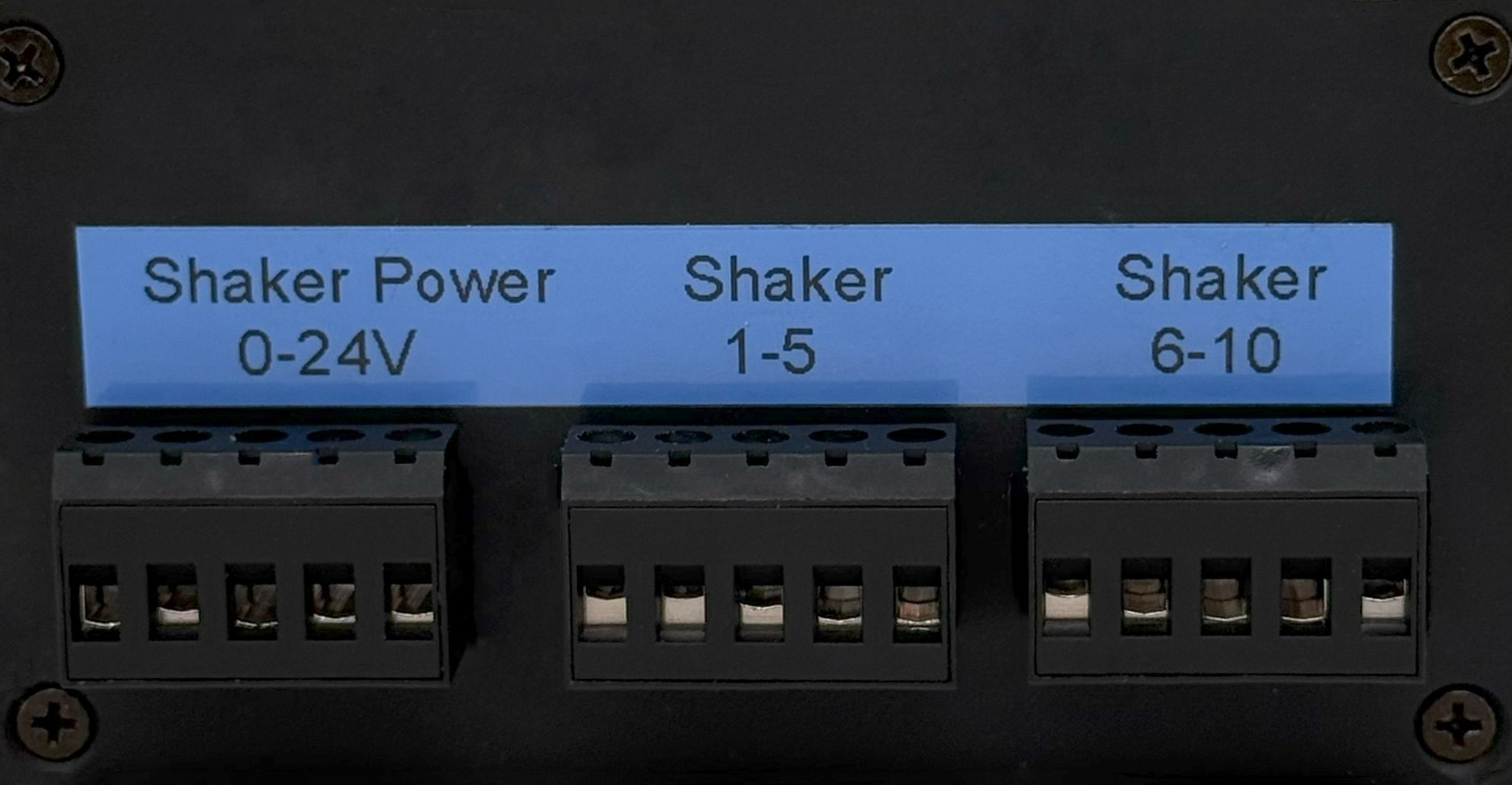
Back Panel
- Shaker Power 0-24V: Connect this terminal to the Positive (+) output of your shaker power supply.
- Shaker 1 - 5: Positive (+) output terminals for shaker strings 1 through 5 (ordered left to right).
- Shaker 6 - 10: Positive (+) output terminals for shaker strings 6 through 10 (ordered left to right).
Note: The negative (-) wires from your physical shakers should be routed directly back to the Ground (-) terminal of your shaker power supply.
Network & IP Setup
The Shaker Control System uses a fixed, static IP address by default to ensure reliable connectivity in cinema environments.
Out of the box (or after a Factory Reset), the system is configured with the following parameters:
- IP Address:
172.16.90.90 - Gateway:
172.16.1.1 - Subnet Mask:
255.255.0.0
Note: To connect to the Web UI, ensure your computer or management laptop is on the same subnet
(e.g. set your laptop to 172.16.90.100 with subnet mask 255.255.0.0), then
navigate to http://172.16.90.90 in your web browser.
Button & LED Guide
The front panel features a single tactile button and a multi-color RGB Status LED to provide immediate hardware diagnostics without needing the Web UI.
Status LED Codes
- Solid Blue System is booting or waiting for network connection.
- Solid Green System Ready (Shakers are currently paused / disabled).
- Breathing Green System Active (Shakers are running and actively monitored).
- Blinking Red System Error (Overcurrent or defect detected).
- Pulsing Blue Reboot sequence initiated (Release button now to reboot).
- Fast Blink Blue Factory Reset initiated (Hold to clear network/IP settings).
Hardware Button Functions
| Action | Result |
|---|---|
| Short Press (< 3 seconds) | Shaker Power Toggle: Toggles the main shaker relay ON or OFF locally. |
| Hold (3 - 10 seconds) | Soft Reboot: Safely restarts the microcontroller (LED pulses blue). |
| Long Hold (> 10 seconds) | Factory Reset: Clears WiFi/IP configurations (LED blinks rapidly). |
Web Interface: Dashboard
The Dashboard is the central monitoring hub of your Shaker Control unit.
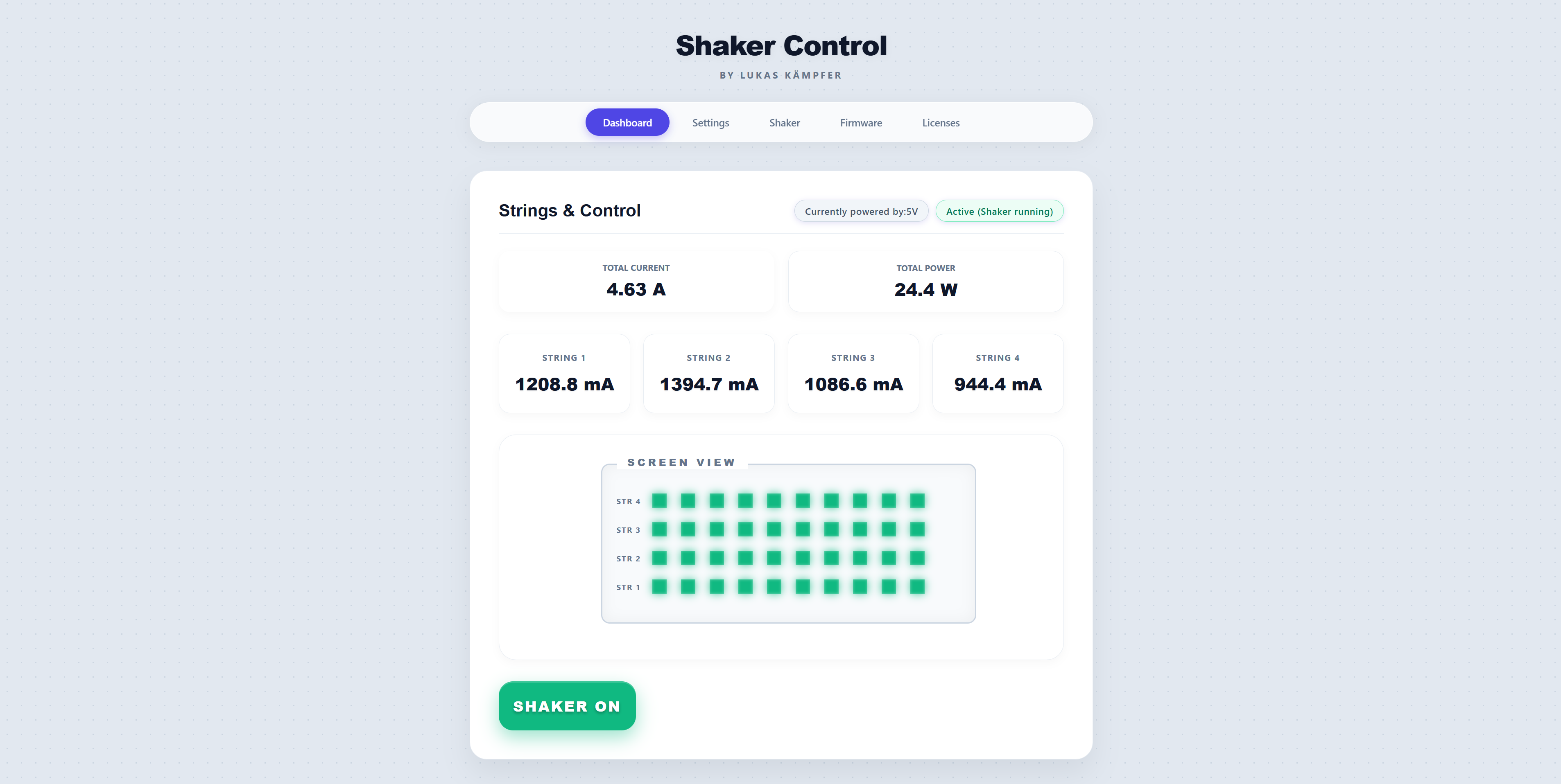
- Total Power: Displays the aggregated real-time current (Amps) and calculated power (Watts) across all strings.
- String Telemetry: A grid showing the live current draw of each individual string (1 through 10).
- Cinema View: A visual layout representing the physical shakers mounted behind the screen. Green icons indicate normal operation, grey indicates the system is paused, and red/orange highlight defective or overloaded shakers.
- Shaker Power Button: A large toggle at the bottom allows you to instantly enable or disable power to the entire shaker array.
Web Interface: System Settings
The Settings page provides access to all fundamental configuration parameters for your controller.
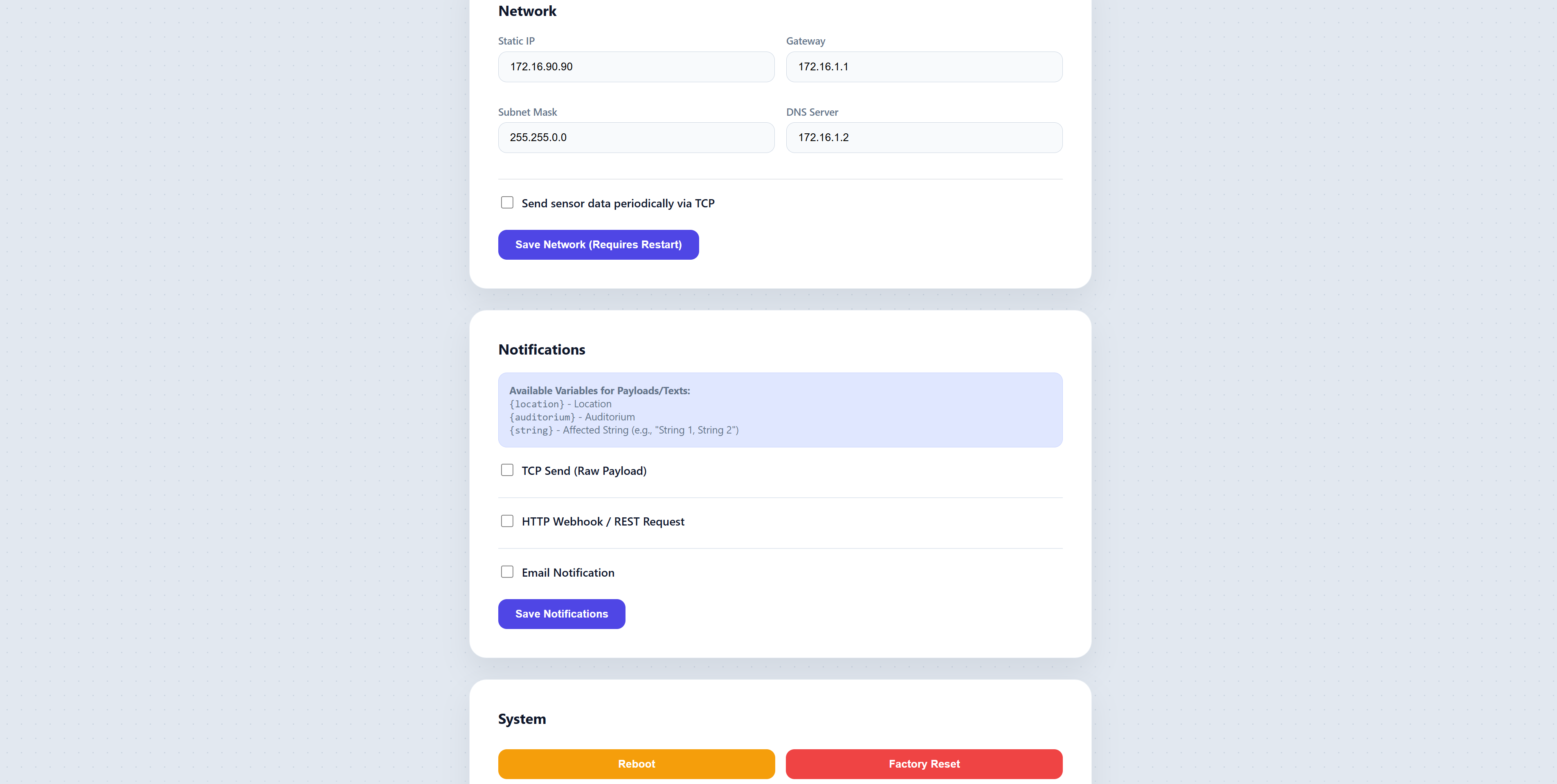
Basic & Network Configuration
- Location & Auditorium: Assign a human-readable location (e.g., "Cinema City") and room name (e.g., "Screen 1"). These names are included in all automated alarms for easy identification.
- System Language: Switches the Web Interface language (e.g., English, German).
- Static IP Settings: Enter your exact network parameters (IP, Gateway, Subnet Mask, DNS Server).
TCP Telemetry
- Send JSON to TCP Client: Enable this to push live sensor telemetry (JSON) to an external TCP socket. Configure the target IP, Port, and sending interval in milliseconds.
Custom Webhooks (HTTP Notifications)
- Enable HTTP Request on Alarm: If enabled, the controller will dispatch an HTTP POST/GET request to an external server whenever a defect or overcurrent occurs.
- IP / Host & Port: The destination server address.
- Method & Body: Choose POST or GET, and define the custom JSON/String payload to be sent.
E-Mail Notifications
- Enable E-Mail Notifications: Master switch to enable or disable the email alert subsystem.
- E-Mail Mode:
- Plug & Play: Secure Cloud routing (License required, highly recommended).
- Custom SMTP: Enter your own corporate SMTP server IP, Port, Username, and Password to send emails natively from the controller.
- Recipient (To): The email address(es) that should receive alarms. Multiple addresses can be separated by commas.
Web Interface: Shaker Logic
This page allows you to perfectly calibrate the hardware limits and error-detection algorithms to match your physical shaker array.
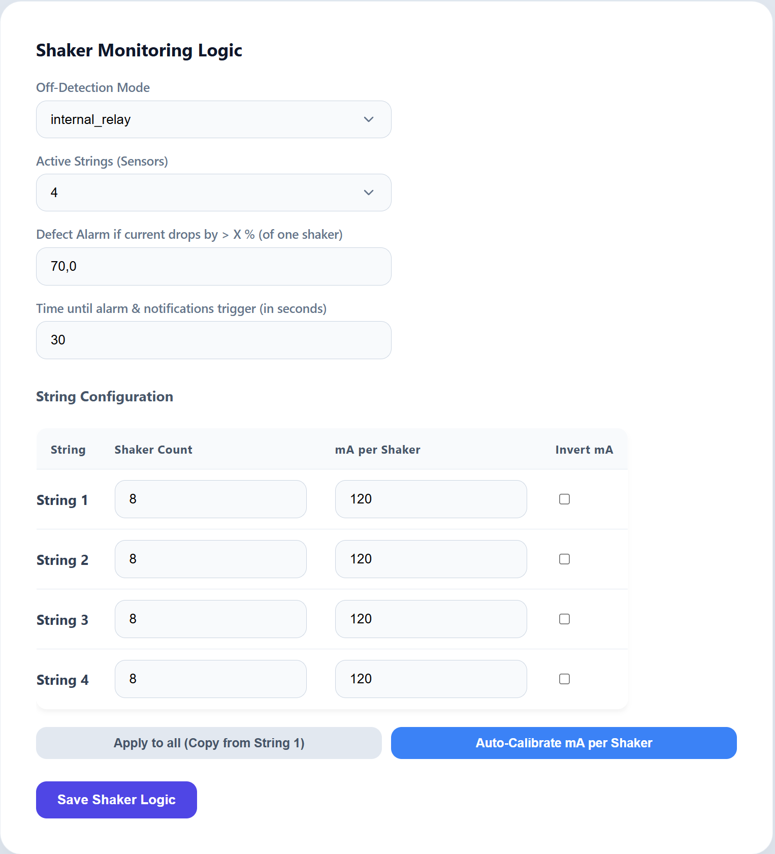
Off-Detection & Calibration
- Off-Detection Mode: Informs the algorithm how to detect when the entire cinema
system is intentionally powered off (e.g., between movies). Options:
- Internal Relay: Assumes shakers are off when the built-in relay is switched off.
- Voltage Drop: Detects when the external amplifier's voltage drops to 0V.
External Control Info: If power is controlled externally via cinema automation, select the Internal Relay mode and use theRELAY=1andRELAY=0TCP commands so the system tracks the power state correctly. - Active Strings (Sensors): Defines how many of the 10 internal sensors are physically wired. Unused strings are completely ignored by the alarm system.
- Defect Threshold (%): If the actual measured current on any string drops below the calculated "Expected Current" by this percentage, a Defect is registered.
- Time until alarm (Seconds): The current must remain below the threshold continuously for this duration before an alarm is dispatched. This prevents false alarms caused by brief current fluctuations during startup and shutdown sequences.
String Configuration
For each active string, you must define:
- Shakers per string: The exact physical count of shakers wired to this string.
- Target Current per Shaker (mA): The nominal current consumption of a single shaker. The system multiplies this value by the shaker count to determine the "Expected Current".
Web Interface: Firmware Updates
Keeping your system up to date is easy via the Over-The-Air (OTA) interface.
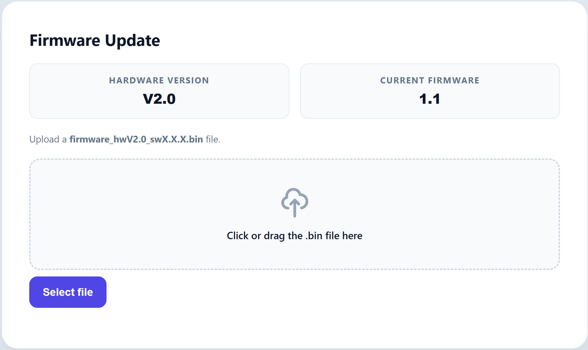
Simply navigate to the Firmware page, click Select File, choose the provided `.bin` firmware file, and click Install Update. The system will flash the update and automatically reboot.
Web Interface: Licensing
Certain advanced features require a valid license key generated specifically for your device hardware.
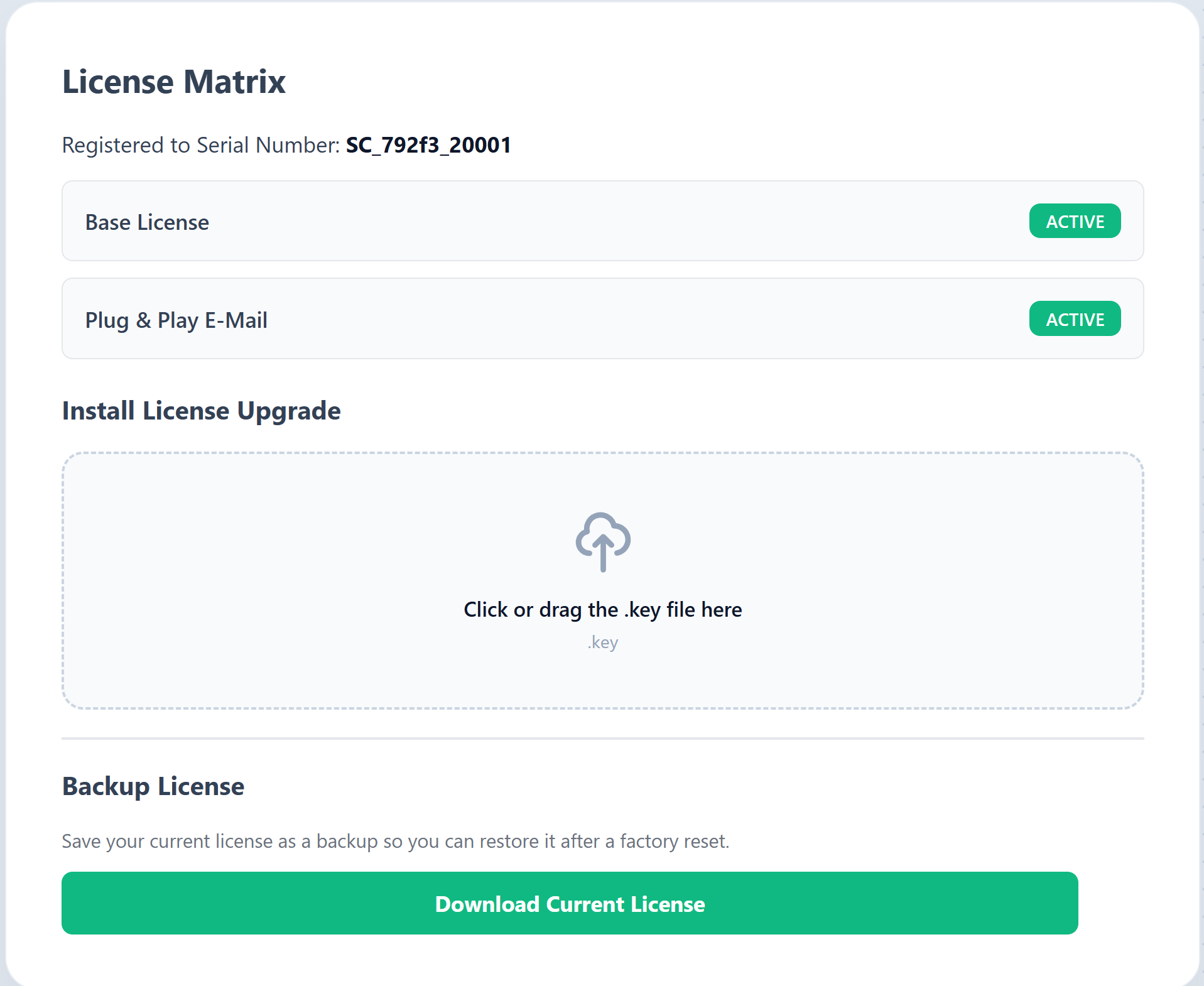
Once you receive your new .key license file from your contact person, simply drag and drop
it into the upload area on this page and click Install License Upgrade. The system will
instantly verify the file and unlock your new features.
Automation API (TCP Commands)
The Shaker Control System supports a direct, lightweight TCP API. This is the standard method used to seamlessly integrate the board into existing cinema automation systems (e.g., Q-SYS, Crestron, or custom control software).
The local TCP Command API server is always active and listens on Port 5555. You can send
plain-text command strings terminated by a newline (\n) directly to this port.
| Command | Description | Response |
|---|---|---|
RELAY=1 or RELAY ON |
Engages the main hardware relay, allowing power to flow to the shakers. | OK: RELAY ON |
RELAY=0 or RELAY OFF |
Disengages the main hardware relay, cutting power to all shakers. | OK: RELAY OFF |
PING or HELLO |
Heartbeat / connection check. | HELLO SHAKER_SYSTEM |